SRRP Injection MoldingShijiazhuang, China · Global RFQ ↗

Core injection molding capabilities

Three connected systems. One accountable production path.

Each system answers a different buyer question: can the part be molded, can the process be approved, and can the same condition be supplied again.

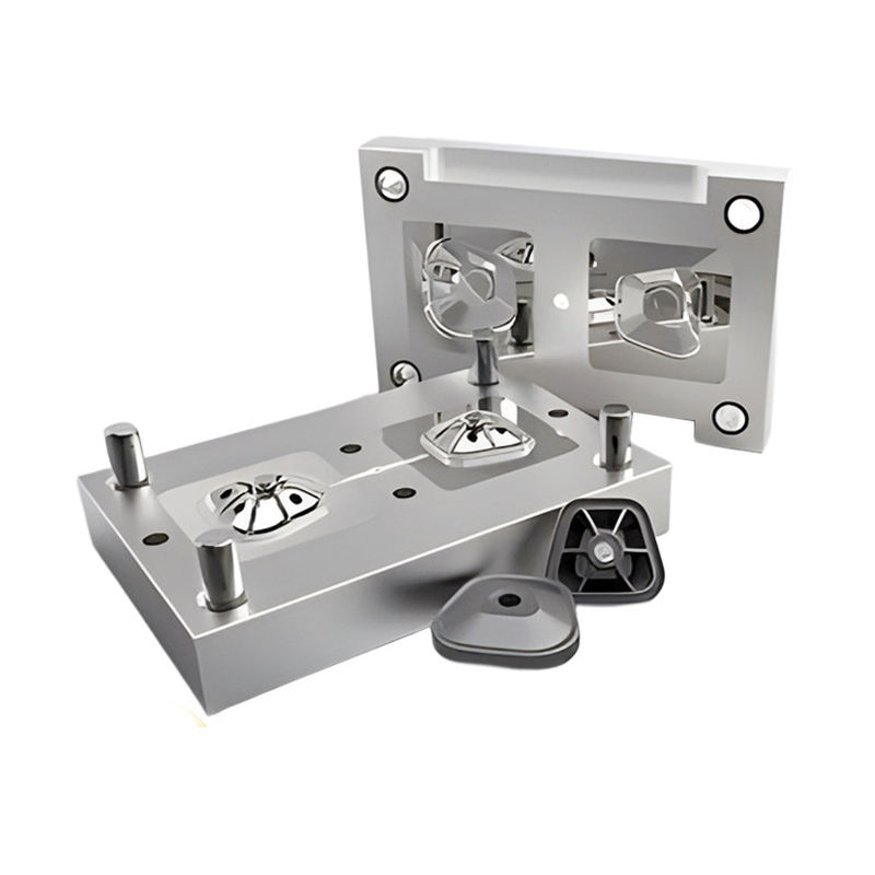
Custom plastic injection mold and first molded parts

01 / DFM + mold development

Engineer the part before steel is committed

Review wall thickness, draft, ribs, bosses, undercuts, parting, gate direction, resin behavior and critical tolerances before mold construction and trial planning.

Explore DFM and tooling
Injection molding equipment in customer-supplied authorized-partner manufacturing media

02 / Production molding

Hold the approved molding condition

Align resin handling, machine and mold setup, first-piece checks, visual criteria and critical dimensions before the production lot is released.

Explore production molding
Production molded parts being inspected and prepared for supply

03 / Validation + finished supply

Make approval evidence usable after T1

Connect trial feedback, dimensional evidence, approved samples, secondary operations, packing and traceability to the released production part.

Explore finished supply
Existing injection mold prepared for condition and transfer review

04 / Existing mold transfer

Move production without losing part history

Review mold records, physical condition, equipment fit, resin, approved samples and revalidation needs before production responsibility changes.

Explore mold transfer

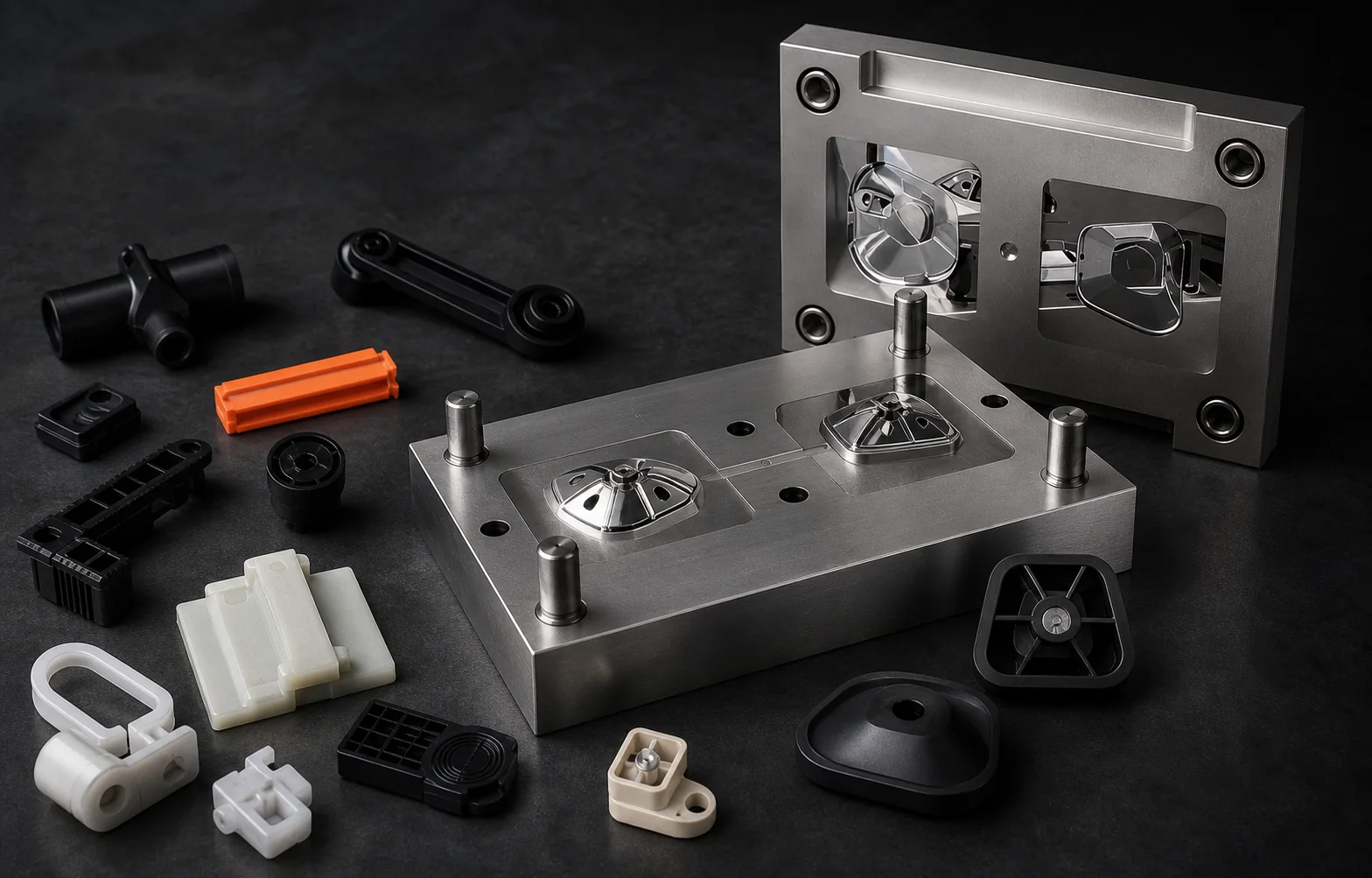
Representative molded geometries

What we mold is defined by your application.

These examples communicate manufacturable geometry—not SKUs or ready-made products. Final resin, dimensions, tolerances, tooling concept and capacity are confirmed against your files, use conditions and annual demand.

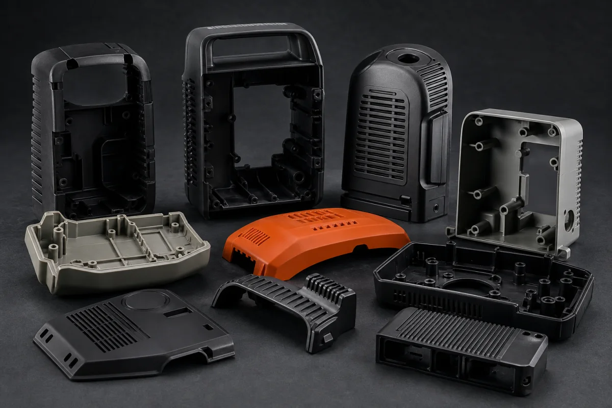
Representative custom injection molded housings, covers and enclosures
Example geometry / housings01

Housings, covers & enclosures

Protective and structural shells developed around ribs, bosses, fastening, mating interfaces, appearance and service.

Start with your housing
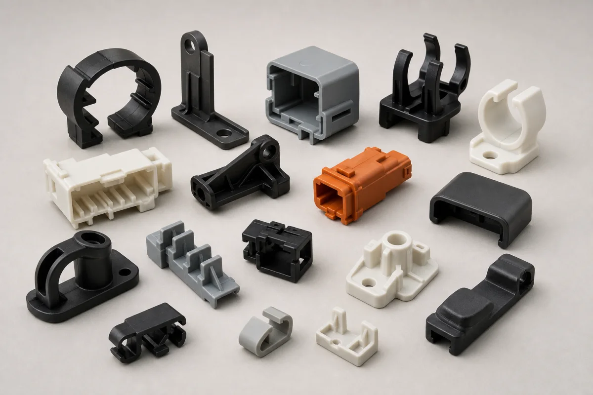
Representative custom injection molded clips, brackets and mounting components
Example geometry / functional02

Clips, brackets & mounts

Functional parts reviewed around snap behavior, load paths, assembly sequence, creep, draft and stable release.

Start with your functional part
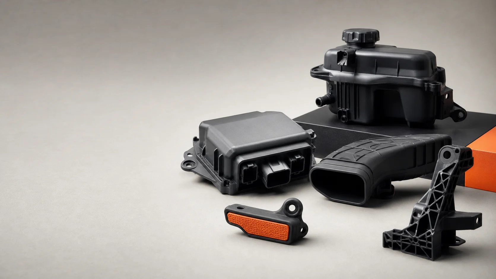
Representative custom injection molded connector housings and interface components
Example geometry / interfaces03

Connectors & interface components

Mating and locating parts where critical dimensions, feature position, material behavior and inspection strategy matter.

Start with your interface
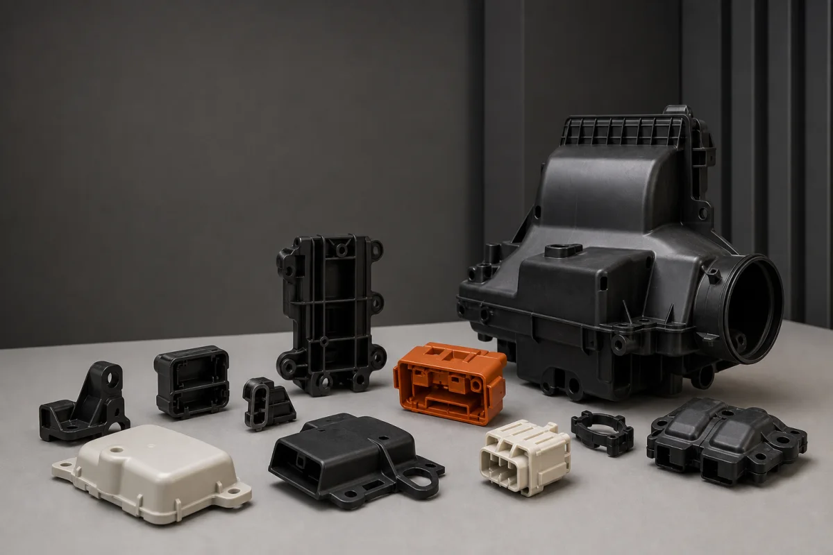
Representative structural and complex custom injection molded plastic parts
Example geometry / structural04

Structural & complex molded parts

Parts with ribs, bosses, deep features or side actions where tooling logic, warpage risk and repeatability must be aligned.

Start with your complex part

Manufacturing evidence

Four documented moments from supplied manufacturing media.

These frames connect the capability story to visible work. Exact equipment range, tolerances and output are confirmed against each drawing rather than presented as universal numbers.

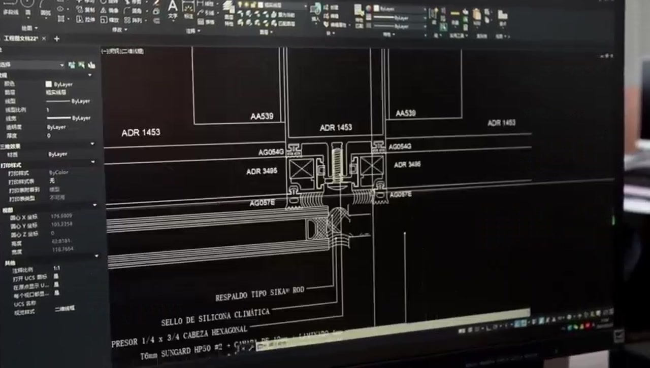
CAD detail shown in customer-supplied authorized-partner film
01 / Engineering

CAD + requirement review

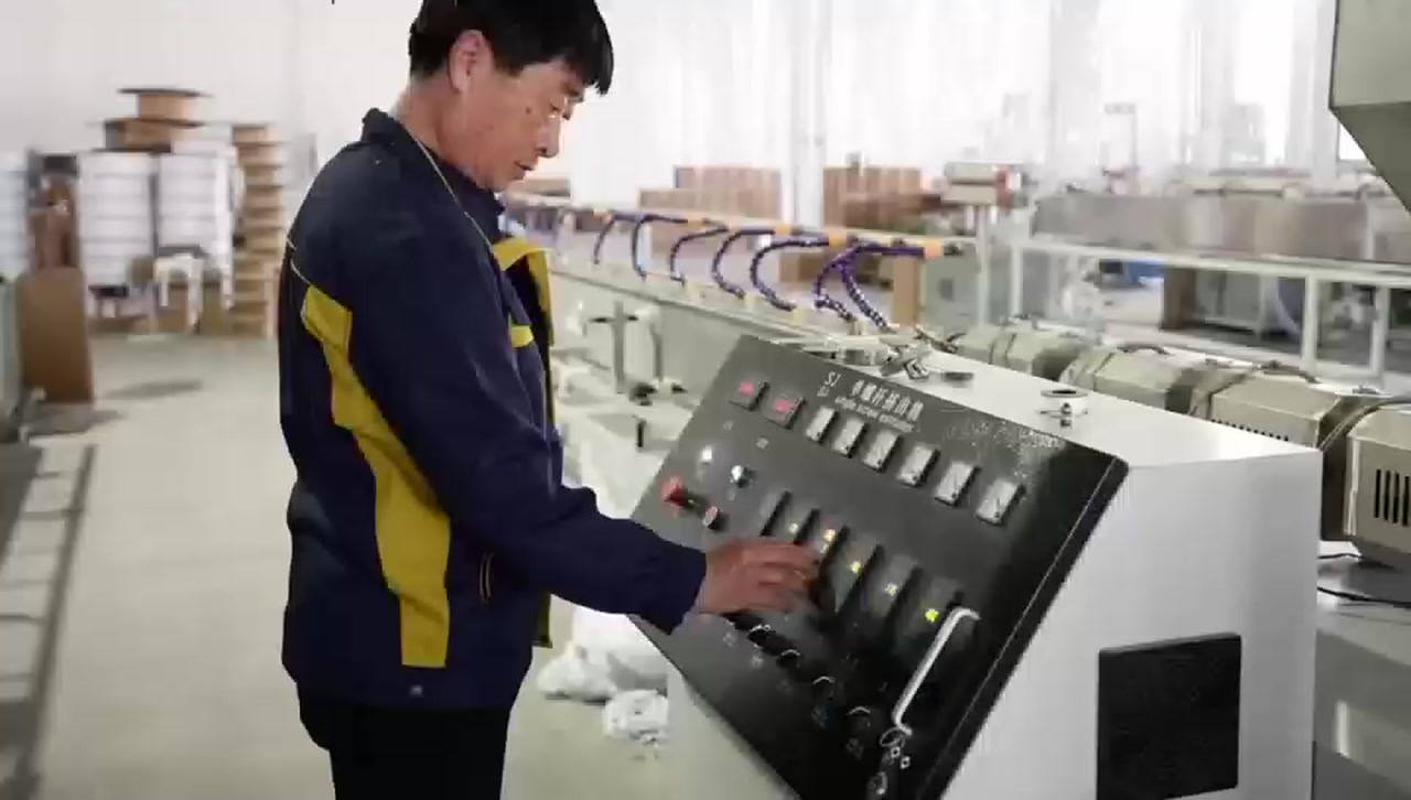
Production equipment operated in customer-supplied manufacturing film
02 / Production

Process setup + operation

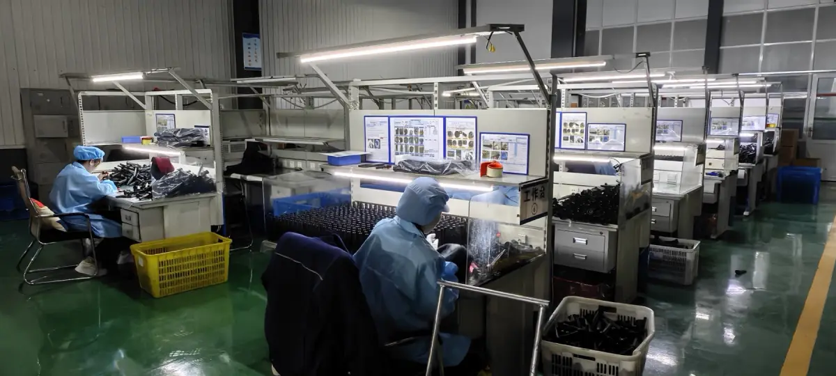
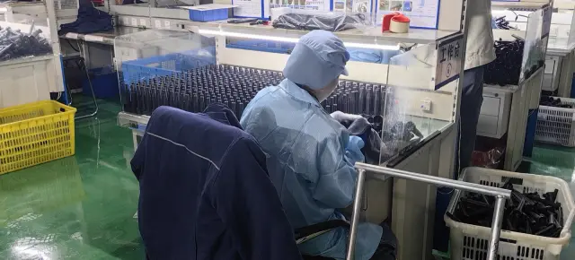
Operator checking a production component at a documented workstation
03 / Part control

Handling + inspection

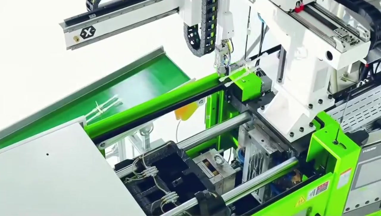
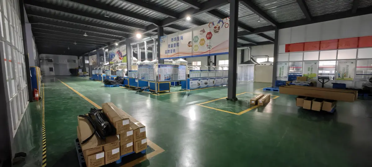
Injection molding equipment shown in customer-supplied partner film
04 / Molding

Injection equipment in context

Manufacturing-film stills supplied by the customer for authorized partner use. Machine tonnage, mold size, material grade, achievable tolerance and production timing are reviewed per project and confirmed in the quotation.

Working sequence

Make every handoff visible.

A reliable part is the result of a reliable sequence. These five moments give the customer and factory team the same decisions to align.

01 / BRIEF

Understand

Drawing, sample, application and volume context.

02 / REVIEW

Define

Material route, DFM, critical features and open questions.

03 / TOOLING

Prepare

Mold concept, steel release and trial plan with approval points.

04 / FIRST-OFF

Approve

Trial parts, inspection results and customer feedback.

05 / SUPPLY

Repeat

Release, packing, delivery and reorder rhythm.

Engineering conversation

Bring the constraint that matters most.

The starting point can be a new CAD model, an unstable molded component, a tool-transfer program or a part that is difficult to source consistently.

Input

Drawing or sample

Geometry, photos, mating parts and any existing specification.

Environment

Application conditions

Load, temperature, fluids, UV, assembly and expected life.

Commercial

Volume + delivery

Prototype need, annual volume, order pattern and destination.

Approval

Evidence required

Critical dimensions, reports, samples, packing and traceability.

Ready for a useful first review?

Start with the part or problem you already have.

Send a CAD file, drawing, sample or concise brief. We will focus the first review on moldability, resin, volume and approval risk.

Request engineering review